1. Built in CPU for digital control, increasing stability by 60%
The PDA series products adopt precise software algorithms, combined with high-speed CPUs, to achieve complete digital control, reducing the application of a large number of components. Compared to brake units controlled by analog circuits, the stability and reliability of PDA series products have been improved by over 60%.
2. Select IGBT and heat sink according to UL standards in the United States for safer and more reliable operation
The PDA series products strictly follow the UL safety standards in the United States, using high-quality IGBTs and heat sinks, and are equipped with four protection methods: overheating, overcurrent, short circuit, and overvoltage, making them safer and more reliable.
3. High standard production processes create higher quality brake units
Every industrial design of the PDA series products has undergone repeated consideration, in order to meet various complex working conditions, fully utilize the characteristics of various components, continuously optimize the internal structure, and ensure the stability, reliability, and high-quality user experience of the products.
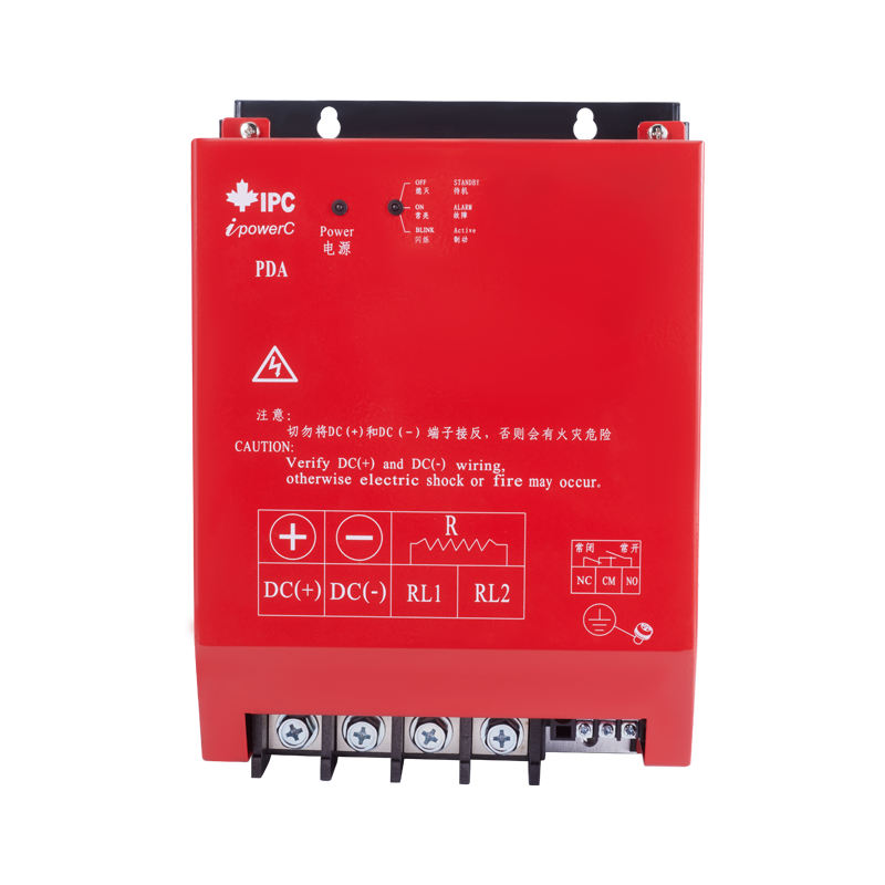
4. Humanized design, adding normally open and normally closed alarm contacts
Fully considering user needs, users do not need to modify the circuit design and can directly connect the alarm device, which facilitates system design and monitoring for users.
5. Simple selection, no need for complex calculations
Based on twelve years of electrical design and application experience, our reliable brake unit selection method allows users to purchase the correct product without the need for complex and tedious calculations.
Item | Specification |
Power Supply | |
Grid Voltage | Three-phase 220V/380V/660VAC, allowable voltage fluctuation range: ±15% (please refer to the specification selection table) |
Grid Frequency | 45Hz~65Hz |
Braking Method | Automatic voltage and current tracking mode (with multiple noise filtering algorithms) |
Response Time | Less than 1ms |
Control | |
Operating Voltage | 330~380VDC (adjustable for 220V class); 590~740VDC (adjustable for 380V class); 980~1200VDC (adjustable for 660V class) |
Loop Voltage | Less than 100V |
Protection Functions | Overheating, overcurrent, short circuit, overvoltage |
Overheat Protection | 75°C (normally open contact for standard model NC-CM, normally closed contact for CM-NO, which changes from open to closed when triggered) |
Overvoltage Protection | When the grid voltage exceeds the set value, the braking unit stops working, and the alarm light is on; all electrical parameters have real-time dynamic indication |
Display and Settings | |
Status Indication | (1) When the bus voltage exceeds the set value, the braking unit stops working, and the alarm light is on; (2) When 2 or more phases are missing (simultaneous phase loss), the braking unit stops working; (3) When the braking unit is working normally, the running indicator is on, and the alarm light is off; (4) When the braking unit is faulty, the alarm light is on |
Operating Voltage Setting | Set by the factory according to customer requirements |
Installation Site and Environment | |
Installation Site | Indoor, altitude not greater than 1000m (derate by 10% for every 1000m increase in altitude), well-ventilated, no corrosive gas and conductive dust |
Ambient Temperature | -10°C~40°C (no direct sunlight) |
Ambient Humidity | Below 90% RH (non-condensing) |
Vibration Intensity | 0.5g or less |
Air Environment | No water droplets, direct sunlight, corrosive gas, flammable gas, oil mist, steam, etc., and not too much dust |
Operating Environment | |
Ambient Temperature | -40°C~70°C |
Ambient Humidity | 5%~95% RH |
Air Environment | No water droplets, direct sunlight, corrosive gas, flammable gas, oil mist, steam, etc., and not too much dust |
Braking Resistor Selection Table (Matching Inverter Models)
Voltage Level (Vac) | Model No. | Power Rating (kW) | Braking Resistor (Tolerance: ±5%) | Enclosure | Dimensions (L×W×H, mm) | Mounting Hole Spacing (L×H, mm) | Mounting Hole Diameter (mm) |
220V | PDA-02-7PSS | 7.5 | 18.4Ω 1.5kW | C1 | 110×56×151 | 60×140 | Φ5.5 |
220V | PDA-02-011S | 11 | 12.5Ω 2.2kW | C1 | 110×56×151 | 60×140 | Φ5.5 |
220V | PDA-02-015S | 15 | 9.2Ω 3.0kW | C2 | 108×95×200 | 98×192 | Φ5.5 |
220V | PDA-02-018S | 18.5 | 7.4Ω 3.7kW | C2 | 108×95×200 | 98×192 | Φ5.5 |
220V | PDA-02-022S | 22 | 6.3Ω 4.4kW | C2 | 108×95×200 | 98×192 | Φ5.5 |
220V | PDA-02-030S | 30 | 4.6Ω 6.0kW | C2 | 108×95×200 | 98×192 | Φ5.5 |
220V | PDA-02-037S | 37 | 3.7Ω 7.4kW | C3 | 191×133×280 | 110×266.5 | Φ7 |
220V | PDA-02-045S | 45 | 3.1Ω 9.0kW | C3 | 191×133×280 | 110×266.5 | Φ7 |
220V | PDA-02-055S | 55 | 2.5Ω 11.0kW | C3 | 191×133×280 | 110×266.5 | Φ7 |
380V | PDA-04-7PSS | 7.5 | 77.8Ω 1.5kW | C1 | 110×56×151 | 60×140 | Φ5.5 |
380V | PDA-04-011S | 11 | 53.0Ω 2.2kW | C1 | 110×56×151 | 60×140 | Φ5.5 |
380V | PDA-04-015S | 15 | 38.9Ω 3.0kW | C1 | 110×56×151 | 60×140 | Φ5.5 |
380V | PDA-04-018S | 18.5 | 31.5Ω 3.7kW | C1 | 110×56×151 | 60×140 | Φ5.5 |
380V | PDA-04-022S | 22 | 26.5Ω 4.4kW | C2 | 108×95×200 | 98×192 | Φ5.5 |
380V | PDA-04-030S | 30 | 19.4Ω 6.0kW | C2 | 108×95×200 | 98×192 | Φ5.5 |
380V | PDA-04-037S | 37 | 15.8Ω 7.4kW | C2 | 108×95×200 | 98×192 | Φ5.5 |
380V | PDA-04-045S | 45 | 13.0Ω 9.0kW | C2 | 108×95×200 | 98×192 | Φ5.5 |
380V | PDA-04-055S | 55 | 10.6Ω 11.0kW | C2 | 108×95×200 | 98×192 | Φ5.5 |
380V | PDA-04-075S | 75 | 7.8Ω 15.0kW | C2 | 108×95×200 | 98×192 | Φ5.5 |
380V | PDA-04-090S | 90 | 6.5Ω 18.0kW | C3 | 191×133×280 | 110×266.5 | Φ7 |
380V | PDA-04-110S | 110 | 5.3Ω 22.0kW | C3 | 191×133×280 | 110×266.5 | Φ7 |
380V | PDA-04-132S | 132 | 4.4Ω 26.4kW | C3 | 191×133×280 | 110×266.5 | Φ7 |
380V | PDA-04-160S | 160 | 3.6Ω 32.0kW | C4 | 230×151×410 | 110×398 | Φ7 |
380V | PDA-04-185S | 185 | 3.2Ω 37.0kW | C4 | 230×151×410 | 110×398 | Φ7 |
380V | PDA-04-200S | 200 | 2.9Ω 40.0kW | C4 | 230×151×410 | 110×398 | Φ7 |
380V | PDA-04-220S | 220 | 2.7Ω 44.0kW | C4 | 230×151×410 | 110×398 | Φ7 |
380V | PDA-04-250S | 250 | 2.3Ω 50.0kW | C4 | 230×151×410 | 110×398 | Φ7 |
380V | PDA-04-280S | 280 | 2.1Ω 56.0kW | C4 | 230×151×410 | 110×398 | Φ7 |
380V | PDA-04-315S | 315 | 1.9Ω 63.0kW | C4 | 230×151×410 | 110×398 | Φ7 |
380V | PDA-04-400S | 400 | 1.5Ω 80.0kW | C4 | 230×151×410 | 110×398 | Φ7 |
Notes:
1. All specifications are subject to technical updates without prior notice.
2. For higher power requirements, multiple units can be connected in parallel.
3. The tolerance of braking resistors is ±5% unless otherwise specified.